SVPWM Principle Thoughts
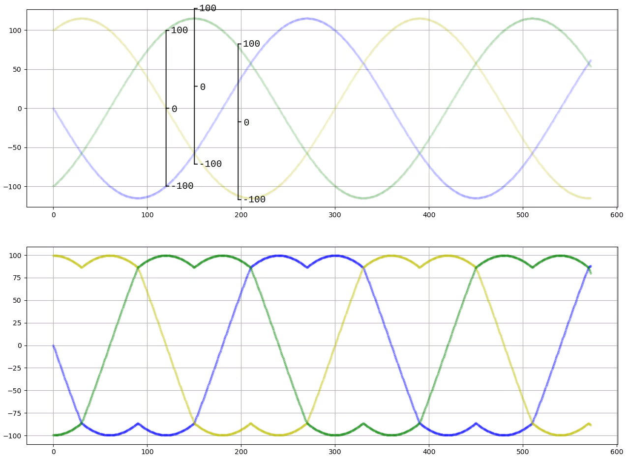
The waveforms of SVPWM and SPWM differ slightly. For example, in the figure below, the standard sine wave represents SPWM, while the one with two peaks represents SVPWM.
The main purpose of using SVPWM is to achieve higher voltage utilization. For instance, with a fixed motor KV value, the higher the voltage, the faster the speed. With the same DC input voltage, SVPWM can increase the voltage output by 15% compared to SPWM.
The principle is straightforward and doesn’t require following the complex process often described online, which involves dividing into six sectors and determining the current angle to calculate the output voltage.
As shown in the figure, with a maximum output limit of ±100%, we first increase the original SPWM output by 15%, causing the three-phase waveforms to exceed the maximum output range.
At this point, adjust the overall offset of the three PWM values up or down (with different offset values at different time points) to ensure that all three PWM values remain within the ±100% range. For the motor, what matters is the relative difference between the three-phase voltages. The overall offset has no effect on the motor.
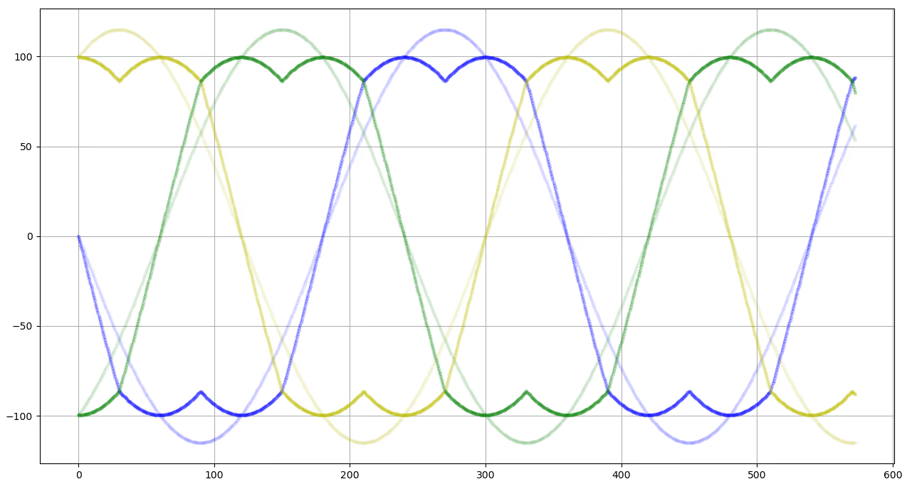
If we shift based on the midpoint (calculating the highest and lowest values to find the median, then shifting accordingly), the output will be a standard SVPWM waveform.

Overlay of the two waveforms:

Script source code for generating the waveform:
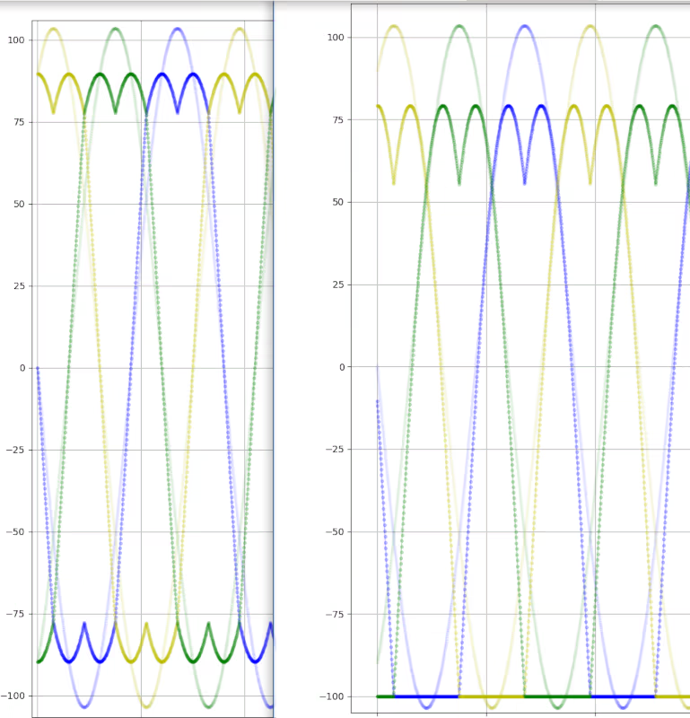
Additionally, we can shift the waveform downward so that at least one phase voltage is minimized, as shown in the right figure below:

Benefits: - For two-shunt current sampling, it improves voltage utilization. - For three-shunt current sampling, it enables earlier current channel switching.
Script:
For more information, please refer to the CDFOC open-source motor controller project:
https://github.com/dukelec/cdfoc

This work is licensed under a Creative Commons Attribution 4.0 International License.
Comments:
Please visit the original link: /svpwm